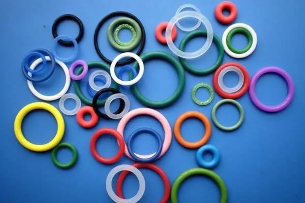
O-ring, also known as O-ring, is a type of rubber ring with a circular cross-sectional shape. O-ring is the most widely used sealing element in hydraulic and pneumatic systems. The O-ring has good sealing performance, which can be used for both static and dynamic sealing; Not only can it be used alone, but it is also a fundamental component of many combined sealing devices. It has a wide range of applications, and if the materials are selected properly, it can meet the requirements of various media and motion conditions.
O-shaped sealing ring is an extrusion type seal, and the basic working principle of the extrusion type seal is to rely on the elastic deformation of the sealing element to create contact pressure on the sealing contact surface. If the contact pressure is greater than the internal pressure of the sealed medium, no leakage will occur, otherwise, leakage will occur.
1. Design principles of O-ring seals
1) Compression rate
The compression rate W is commonly expressed as follows:
W=(do h)/do%
In the formula, do - cross-sectional diameter of the O-ring in free state (mm)
H - The distance between the bottom of the O-ring groove and the sealed surface, i.e. the cross-sectional height of the O-ring after compression (mm).
When selecting the compression ratio of the O-ring, the following three aspects should be considered:
a. Sufficient sealing contact area is required
b. Minimize friction as much as possible
c. Try to avoid permanent deformation.
It is not difficult to see from the above factors that there are contradictions between them. A high compression rate can result in high contact pressure, but an excessive compression rate will undoubtedly increase sliding friction and permanent deformation. If the compression rate is too small, it may be due to the coaxiality error and O-ring error of the sealing groove not meeting the requirements, resulting in the disappearance of some compression amount and causing leakage. Therefore, when choosing the compression ratio of the O-ring, it is necessary to weigh various factors. Generally, the compression rate of static seals is greater than that of dynamic seals, but its extreme value should be less than 30% (related to rubber materials), otherwise the compression stress will significantly relax and excessive permanent deformation will occur, especially in high temperature conditions.
The selection of compression ratio W for O-ring seals should consider the usage conditions, such as static or dynamic seals; Static sealing can be divided into radial sealing and axial sealing; The leakage gap of radial seals (or cylindrical static seals) is the radial gap, while the leakage gap of axial seals (or planar static seals) is the axial gap. Axial sealing is divided into two situations based on whether the pressure medium acts on the inner diameter or outer diameter of the O-ring: internal pressure and external pressure. The increase in internal pressure causes stretching, while the external pressure reduces the initial stretching of the O-ring. The different forms of static sealing mentioned above have different directions of force exerted by the sealing medium on the O-ring, so the pre pressure design is also different. For dynamic seals, it is necessary to distinguish between reciprocating motion and rotary motion seals.
1. Static sealing: Like reciprocating sealing devices, cylindrical static sealing devices generally take W=10% -15%; The flat sealing device takes W=15% -30%.
For dynamic seals, there are three situations:
a. The reciprocating motion seal generally takes W=10% -15%.
b. When selecting the compression ratio for rotary motion seals, the Joule heat effect must be considered. Generally speaking, the inner diameter of the O-ring used for rotary motion is 3-5% larger than the shaft diameter, and the compression ratio of the outer diameter is W=3% -8%.
c. O-rings are used for low friction movements. In order to reduce frictional resistance, a smaller compression ratio is generally chosen, which is W=5-8%. In addition, it is also necessary to consider the expansion of rubber materials caused by the medium and temperature. Usually, beyond the given compression deformation, the maximum allowable expansion rate is 15%. Exceeding this range indicates that the material selection is not appropriate, and O-rings of other materials should be used instead, or the given compression deformation rate should be corrected. The specific values of compression deformation are generally formulated or recommended by countries based on their own usage experience.
2) Stretching amount
After being installed in the sealing groove, the O-ring generally has a certain amount of stretching. Unlike the compression rate, the amount of stretching also has a significant impact on the sealing performance and service life of the O-ring. A large amount of stretching not only makes it difficult to install the O-ring, but also reduces the compression rate due to changes in the cross-sectional diameter do, leading to leakage. Stretching amount α It can be represented by the following equation:
α= (d+do)/(d1+do)
In the equation
D - Shaft diameter (mm);
D1- Inner diameter of O-ring (mm);
Do - cross-sectional diameter of the O-ring (mm).
3) Contact width
After the O-ring is installed in the sealing groove, its cross-section undergoes compression deformation. The width after deformation and its contact width with the shaft are related to the sealing performance and service life of the O-ring, and too small a value can affect the sealing performance; If it is too large, it will increase friction, generate frictional heat, and affect the lifespan of the O-ring.
The width BO (mm) of the deformed O-ring is related to the compression ratio W and cross-sectional diameter dO of the O-ring, which can be calculated using the following equation
BO={1/(1-W) -0.6W} dO (W takes 10% -40%)
The width b (mm) of the contact surface between the O-ring and the shaft also depends on W and dO:
B=(4W2+0.34W+0.31) dO (W takes 10% -40%)
For O-ring seals with high friction limitations, such as pneumatic seals and hydraulic servo control component seals, friction can be estimated based on this.
2. Design of O-ring
The vast majority of O-rings are made of synthetic rubber material. The size of synthetic rubber O-rings is determined by international standards (ISO3601/1), national standards, and organizational standards. For example, some countries divide the size series of O-rings into four series: P series (for sports use), G series (for fixed use), V series (for vacuum use), and ISO series (for general industrial use).
The inner diameter, cross-sectional diameter, dimensions, and tolerances of O-rings in China are specified in GB/T34542.1-1992.
The sealing reliability of the sealing device mainly depends on the compression amount of the O-ring. In general, this compression amount is very small, ranging from tens of micrometers to tens of micrometers, which requires high accuracy in the dimensional tolerance of the O-ring. Therefore, the O-ring needs to be processed using high-precision molds, and it is necessary to accurately grasp the shrinkage rate of the O-ring material as the design basis. Generally, the shrinkage rate of the O-ring can only be obtained through actual measurement. It is worth noting that:
1) The shrinkage rate of the O-ring section is very small and is generally not considered. Only when its cross-sectional diameter is greater than 8mm, it should be considered.
2) Under certain formula and process conditions, the shrinkage rate of the O-ring will decrease with the increase of material hardness and also increase with the decrease of its inner diameter. An O-ring with medium hardness (HS75 ± 5) and medium size (inner diameter d=40-70mm) has a shrinkage rate of approximately 1.5% on the inner diameter.
Generally, in static sealing situations, a sealing ring with a smaller cross-section can be selected; In dynamic sealing situations, a sealing ring with a larger cross-section should be selected. Usually, when the pressure is high and the gap is large, materials with higher hardness should be selected; You can also choose a material with average hardness and install a PTFE retaining ring.
3. Design of O-ring sealing groove
The compression and stretching amount of an O-ring seal is ensured by the size of the sealing groove. After the O-ring seal is selected, its compression, stretching amount, and working state are determined by the groove. Therefore, groove design and selection have a significant impact on the sealing performance and service life of the sealing device. Groove design is the main content of O-ring seal design.
Sealing groove design includes determining the shape, size, accuracy, and surface roughness of the groove, as well as determining the relative motion clearance for dynamic sealing. The principle of groove design is: easy processing, reasonable size, easy accuracy assurance, and convenient installation and disassembly of O-ring. The common groove shape is a rectangular groove.
1) Groove shape
The rectangular groove is the most commonly used groove shape for hydraulic and pneumatic O-ring seals. The advantage of this groove is that it is easy to process and ensures that the O-ring has the necessary compression. In addition to rectangular grooves, there are also V-shaped, semi-circular, dovetail shaped, and triangular grooves.
The cross-sectional shape of a triangular groove is an equilateral right triangle with M as the right angle side. The cross-sectional area is approximately 1.05-1.10 times the cross-sectional area of the O-ring. The triangular groove sealing device is applied in countries such as the United Kingdom, the United States, and Japan. The design principle is that the nominal dimensions of the inner diameter of the O-ring seal are equal.
The sealing groove can be opened on the shaft or on the hole; The axial seal is grooved on a flat surface.
2) Design of slot width
The size parameters of the sealing groove depend on the size parameters of the O-ring seal.
The size of the groove can be calculated by volume, and usually requires the size of the rectangular groove to be about 15% larger than the volume of the O-ring. This is because:
a. After the O-ring is installed in the groove, it bears a compression of 3% -30%, while the rubber material itself is incompressible, so there should be space to accommodate the deformed part of the O-ring.
b. In addition to the expansion of the rubber material caused by immersion in the oil, the O-ring in the oil may also experience expansion of the rubber material as the working temperature of the liquid increases. So the groove must have a certain margin left.
c. Be able to adapt to the slight rolling phenomenon that may occur with the O-ring in motion. It is generally believed that it is necessary to leave an appropriate gap between the assembled O-ring and the groove wall. But this gap cannot be too large, otherwise it will become a harmful "clearance" under the action of alternating pressure, which will increase the wear of the O-ring.
The groove should not be too narrow. If the O-ring section fills the groove section, the frictional resistance during movement will be particularly high, and the O-ring cannot roll, causing serious wear. The groove should not be too wide, because when the groove is too wide, the movement range of the O-ring is large and it is also prone to wear. Especially during static sealing, if the working pressure is pulsating, then the static seal will not be static. It will swim at the same pulsating frequency in an unsuitable wide groove, causing abnormal wear and failure of the O-ring quickly.
The cross-sectional area of the O-ring should account for at least 85% of the rectangular groove cross-sectional area, and the groove width must be greater than the maximum diameter of the O-ring after compression deformation. In many cases, it is ensured that the groove width is 1.1-1.5 times the cross-sectional diameter of the O-ring. When the internal pressure is high, a retaining ring must be used, and the groove width should also be increased accordingly.
Different working methods include radial or axial sealing, dynamic or static sealing, hydraulic or pneumatic sealing, and different sizes of sealing grooves. The size series of O-ring seals and sealing grooves in China is based on the national standard GB/T3452.3-1988, and groove sizes can also be calculated and designed according to the requirements for compression and stretching of the sealing ring.
3) Design of groove depth
The depth of the groove mainly depends on the required compression rate of the O-ring seal. The depth of the groove, combined with the gap, must be at least less than the cross-sectional diameter of the O-ring in the free state to ensure the required deformation of the O-ring compression for sealing.
The compression deformation of the O-ring is determined by the compression deformation at the inner diameter of the O-ring δ’ Compression deformation at the outer diameter δ’’ Composition, i.e δ=δ’+δ’’。 When δ’=δ’’ When the section center of the O-ring coincides with the section center of the groove, and the circumference of the two center circles is equal, it indicates that the O-ring was not stretched during installation. If δ’>δ’’, The circumference of the center circle of the O-ring section is smaller than the circumference of the groove center circle, indicating that the O-ring is installed in the groove in a stretched state; if δ’<δ’’, The circumference of the center circle of the O-ring section is greater than the circumference of the groove section center circle. At this point, the O-ring is subjected to circumferential compression, and during disassembly, the O-ring will experience bouncing.
When designing the groove depth, the use of the O-ring should be determined first, and then a reasonable compression deformation rate should be selected.
4) Design of Notches and Bottom Fillets
The rounded corners at the outer edge of the groove are designed to prevent scratches during O-ring assembly. It generally adopts a smaller fillet radius, which is r=0.1-0.2mm. This can avoid the formation of sharp edges at this point, and the O-ring cannot be squeezed out of the gap, making it stable to place the retaining ring.
The rounded corners at the bottom of the groove are mainly designed to avoid stress concentration at that location. The value of the fillet radius can be taken as R=0.3-1mm for dynamic sealing grooves, and half of the cross-sectional diameter of the O-ring for static sealing grooves, i.e. R=d/2.
5) Gap
There must be a gap between the reciprocating piston and the cylinder wall, which is related to the working pressure of the medium and the hardness of the O-ring material. The gap is too small, making manufacturing and processing difficult; If the gap is too large, the O-ring will be squeezed into the gap and damaged. Generally, the larger the internal pressure, the smaller the gap; The greater the hardness of the O-ring material, the larger the gap. When the gap value is at the bottom left of the curve, there will be no gap bite or "extrusion" phenomenon.
The given value of the gap is closely related to the manufacturing accuracy of the part.
6) Roughness of groove wall
The surface roughness of the sealing groove directly affects the sealing performance of the O-ring and the craftsmanship of the groove. The O-ring for static sealing does not move during operation, so the roughness of the groove wall is Ra=6.3-3.2 μ m. For O-rings used for reciprocating motion, due to frequent rolling in the groove, the roughness of the groove wall and bottom should be lower, with a requirement of Ra=1.60 μ Below m. The O-ring used for rotational motion is generally stationary in the groove, and the required roughness of the shaft is Ra=0.40 μ M or polishing.
4. Retaining ring
As the pressure increases, the O-ring and retaining ring compress each other. Due to their elasticity, both deform simultaneously, and this deformation first extends towards their upper and lower corners until the pressure exceeds 10.5MPa. This deformation always occurs between the two without causing the retaining ring to "squeeze out". The degree of improvement in pressure bearing capacity varies depending on the material and structural form of the retaining ring. When the pressure is high enough, the retaining ring will also experience "extrusion" phenomenon.
After using a retaining ring for the O-ring, the working pressure can be greatly increased. The static sealing pressure can be increased to 200-700MPa; The dynamic sealing pressure can also be increased to 40MPa. The retaining ring also helps the O-ring maintain good lubrication. If subjected to unidirectional compression, use a retaining ring on the bearing side; If subjected to bi-directional compression, use two retaining rings. For static seals, a retaining ring is not used when the internal pressure is below 32MPa, and a retaining ring is used when the value exceeds this value. Although the use of a retaining ring can prevent the O-ring from experiencing "gap bite", it will increase the frictional resistance of the sealing device.
The materials of the retaining ring include leather, hard rubber, and polytetrafluoroethylene, as well as nylon 6 and nylon 1010. And PTFE retaining rings are the most commonly used. PTFE has the following advantages as a retaining ring material.
1) High working accuracy.
2) Excellent chemical resistance, suitable for almost all media.
3) There is no hardening or damage phenomenon.
4) Wide temperature range for use.
5) Low friction.
6) No water absorption.
7) No aging occurs at a temperature of 177 ℃.
5. Use, installation, and leakage of O-ring
1) Use of O-ring
O-ring is widely used at the joints of various hydraulic and pneumatic components, cylinder surfaces, and flange surfaces. For O-rings used during movement, when the working pressure is greater than 9.8Mpa and subjected to unidirectional pressure, a retaining ring should be installed on the other side of the O-ring in the direction of pressure; If subjected to bidirectional compression, place a retaining ring on both sides of the O-ring. To reduce friction, wedge-shaped retaining rings can also be used. When the pressure liquid is applied from the left, the right retaining ring is pushed up, and the left retaining ring does not come into contact with the sealed surface, thus reducing the friction force. Overall, the use of retaining rings increases the friction force of the sealing device, and wedge shaped retaining rings are of great significance in reducing this friction force. For fixed O-rings, a retaining ring is also required when the working pressure is greater than 32Mpa.
Original link: https://www.xianjichina.com/special/detail_500354.html
Source: Xianji Network
The copyright belongs to the author. For commercial reprints, please contact the author to obtain

2) Installation of O-ring
The installation quality of O-rings has a significant impact on their sealing performance and service life. Leakage problems are often caused by poor installation.
During the installation process, it is not allowed to have the O-ring scratched, misaligned, or twisted. Before assembly, the sealing groove and sealing mating surface must be strictly cleaned; At the same time, apply lubricating grease to the surface that needs to pass through during the assembly of the O-ring.
In order to prevent the O-ring from being cut or scratched by sharp edges such as sharp corners and threads during installation, a 15 º -30 º lead-in angle should be left at the shaft end and hole end of the installation. When the O-ring needs to pass through the external thread, a special thin-walled metal guide sleeve should be used to cover the external thread; If the O-ring needs to pass through the orifice, the orifice should be inverted into a corresponding diagonal shape to prevent scratches on the O-ring. The slope angle of the groove is generally a=120 º -140 º