General term for pipeline flange joints with sealing performance required for buried steel pipelines and electrical insulation performance required for electrical corrosion protection engineering
Insulated flange is a general term for pipeline flange joints that have both the sealing performance required for buried steel pipelines and the electrical insulation performance required for electrical corrosion protection engineering.
Chinese name Insulating flange Foreign name Insulating flange Brief description of the general characteristics of pipeline flange joints Simple structure, safe use, and reliable performance
Product Introduction
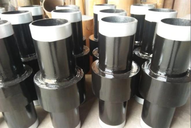
Insulating flange is a general term for pipeline flange joints that have both the sealing performance required for buried steel pipelines and the electrical insulation performance required for electrochemical corrosion protection engineering. It includes a pair of steel flanges, insulation seals between two flanges, flange fasteners and fastener insulation parts, as well as a pair of steel short pipes that have been welded to the two flanges separately.
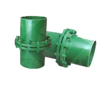
Insulated flanges and insulated joints are products produced for industries such as petroleum and chemical engineering. They have simple structure, safe use, and reliable performance, and have been widely praised by users. Insulated flange products have formed a series, and in special circumstances, they can be designed and manufactured separately according to user requirements.
Product Usage
Insulated flanges are mainly used between gas transmission and distribution pipelines and equipment such as gas pressure regulation, metering, and storage. Their main function is to insulate and isolate each section of the gas transmission and distribution pipeline, as well as between equipment and pipelines, to protect them from chemical corrosion and extend the service life of pipelines and equipment. The product meets the standard of SY/T0516-1997 "Technical Regulations for Design of Insulated Flanges".
Product classification
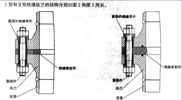
This product is divided into two types based on its insulation sealing components: pressure specific sealing insulation flange (referred to as Type I insulation flange) and self tightening sealing insulation flange (referred to as Type II insulation flange).
Product Features
1. Having the electrical insulation performance required for buried pipeline electrical corrosion protection engineering.
2. Capable of working reliably for a long time under the required temperature and pressure of the pipeline medium, with sufficient strength and sealing performance.
3. Reasonable structure, easy to assemble, disassemble, and replace parts.
Structure and characteristics
The composition of the old type I insulation flange is composed of adding flange insulation gaskets between two butt welded flat flanges, and installing insulation sleeves and insulation bolt gaskets on the fastening connecting bolts. The structural assembly diagram is shown in Figure 1. The flange insulation gasket material is made of oil resistant rubber asbestos board, chloroprene rubber board, fabric based chloroprene rubber board, and polytetrafluoroethylene. The insulation bolt sleeve and bolt insulation gasket are made of high-strength phenolic laminates and compression tubes. Its characteristics are good rigidity, stable insulation performance, and the need for specialized installation positions, resulting in high cost.
New development
Suitable improvements have been made to the structure of the old insulated flange. In urban gas transmission and distribution engineering, improvements are made to address the characteristics of low pressure (PN ≤ 2.5MPa) and pipeline network pressure PN ≤ 0.4MPa in urban gas transmission and distribution engineering. In pipeline transmission and distribution engineering, steel flat flanges are used instead of welded flat flanges. The insulation gasket of the flange is made of materials such as polytetrafluoroethylene, oil resistant rubber asbestos sheet, chloroprene rubber, etc. The insulation sleeve and gasket for fastening bolts will be divided into two parts, and the insulation sleeve will be shortened by half to form an integral high-strength insulation sleeve gasket. As shown in Figure 1, expand the bolt hole of the steel flange through the sleeve gasket to be able to pass through the insulation sleeve gasket; To ensure that the inner diameter of the gasket is suitable for the requirements of the bolts used in the original steel flange, a special type of steel flange is made, and after assembly, it becomes a new type of insulated flange. It can be installed separately or together with the connecting valve; It not only saves engineering costs but also saves on-site installation location, making it a simple and applicable new type of insulation flange with a particularly low cost.
Principle and Performance
The working principle of insulation flange is to use the electrical insulation performance of the insulation gasket and high-strength insulation sleeve gasket in the insulation flange to perform electrical insulation on both sides of the insulation flange. Based on the actual engineering situation, we tested the insulation performance of the insulated flange in accordance with the relevant requirements of the "Technical Regulations for Design of Insulated Flanges" (SY/T0516-1997) and the relevant methods of the "Test Method for Cathodic Protection Parameters of Buried Steel Pipelines" (SYJ23-86). The test results showed that the resistance value of the insulation gasket and the insulation sleeve of the fastening bolt between the insulation working surface can meet the specification requirements.
Usage
This type of insulation flange is used at the building valves of the cathodic protection transmission and distribution network, as well as in buried pipeline valve wells that require potential partition (zone) isolation. The isolation of buried transmission and distribution pipelines can provide a clearer understanding of the cathodic protection situation of each pipeline network; Evaluate the cathodic protection sections (areas) and handle different cathodic protection situations; When the protection potential of adjacent pieces (areas) is the same (or similar) and meets the protection potential requirements, cross bars can be used to connect both sides of the insulation flange for unified protection; When there is a significant difference in the protection potential between adjacent slices (areas) and there are slices (areas) that cannot meet the protection potential requirements, special treatment can be carried out on the slices (areas) that cannot meet the protection potential requirements until they meet the requirements, and then they can be operated continuously in the future.
standard
National standard flange refers to the flange produced in accordance with the national standard of the People's Republic of China, GB/T 9112-9124-2010 Steel Pipe Flanges.
The national standard flange standard was jointly issued by the General Administration of Quality Supervision, Inspection and Quarantine of the People's Republic of China and the National Standardization Administration of China on January 10, 2011, and has been implemented as a recommended standard since October 1, 2011.
GB/T 9112~9124-2010 includes a total of 13 standards:
Replaced the national standard GB/T9112-2000; GB/T10745-1989 standard
GB/T 9112-2010 Steel Pipe Flanges - Types and Parameters
GB/T 9113-2010 Integral Steel Pipe Flanges
GB/T 9114-2010 Threaded Steel Pipe Flanges with Neck
GB/T 9115-2010 Butt Welded Steel Pipe Flanges
GB/T 9116-2010 Flat Welded Steel Pipe Flanges with Neck
GB/T 9117-2010 Steel Pipe Flanges with Neck Socket Welding
GB/T 9118-2010 Butt Welding Ring Neck Loose Sleeve Steel Pipe Flanges
GB/T 9119-2010 Plate type flat welded steel pipe flanges
GB/T 9120-2010 Butt welded ring plate loose sleeve steel pipe flanges
GB/T 9121-2010 Flat Welded Ring Plate Loose Sleeve Steel Pipe Flanges
GB/T 9122-2010 Flared Ring Plate Loose Sleeve Steel Pipe Flanges
GB/T 9123-2010 Steel Pipe Flange Covers
GB/T 9124-2010 Steel Pipe Flanges
technical conditions
The pressure markings specified in this standard are divided into PN markings and Class markings.
PN marking has 12 pressure levels
Respectively: PN2.5; PN6; PN10; PN16; PN25; PN40; PN63; PN100; PN160; PN250; PN320; PN400
The Class tag has 6 pressure levels
Respectively: Class 150; Class 300; Class 600; Class 900; Class 1500; Class 2500
Another meaning of national standard flange is: flange plates produced according to the dimensions, tolerance range, and other requirements of national standards. Different from flange plates not produced according to standard dimensions, which are also known as second standard flanges (some people call non-standard flanges incorrect), some unscrupulous merchants usually reduce the thickness and outer diameter of the flange plate to achieve the purpose of saving materials, and also use waste steel or leftover steel to process flanges, Usually, this type of steel is a waste material with substandard chemical composition and mechanical properties. Some even use black steel plants to produce flanges through private steelmaking. The steelmaking technology used in this type of private steelmaking is outdated and cannot guarantee mechanical and welding properties. When used, it may not be able to weld with the steel pipe, or the steel itself may leak water after welding with cracks, pores, etc. So when purchasing flange plates, try to choose national standard flanges as much as possible. If funds are limited, it is necessary to carefully observe and measure the flange size to avoid being deceived when choosing the second standard flange.
Management methods
1) Each cathodic protection pipeline should have a "Cathodic Protection Operation Management Regulations" that comply with the actual situation of the pipeline, so that daily testing, control, adjustment, maintenance and other aspects of cathodic protection work can be carried out according to this. 2) Keep indoor equipment clean and free from faults, defects, rust, and foreign objects. Implement three diagrams on the wall, namely line direction diagram, protection potential curve diagram, and job responsibility system. 3) After the cathodic protection station is put into operation, the electrical equipment wiring shall not be changed without authorization. If changes are needed, a plan shall be made by the competent department and can only be implemented after approval. 4) Check and measure the potential of the electrified point daily, fill in the operation log, and report the operation status of the cathodic protection station to the production scheduling department. 5) The cathodic protection station shall not interrupt the power transmission to the pipeline, ensuring that more than 98% of the time for power transmission to the pipeline throughout the year. 6) Maintain the potential of the energized point at the specified value and measure the cathodic protection potential along the pipeline. This measurement is conducted once a week during the initial operation of the cathodic protection station, and once every two weeks or once a month thereafter. 7) Measure the natural potential and soil resistivity along the pipeline once a year within the specified time. 8) Check and eliminate pipeline grounding faults to achieve complete cathodic protection for the entire line.